Transformer Impedance Per Phase
It is worth noting that the transformer impedance voltage expressed in percent or per unit is independent of the winding connection. A difference in the ratio of the reactance value to resistance value of the per unit impedance results in a different phase angle of the currents carried by the two paralleled transformers.

Per Unit System Definition Per Unit Representation Of
Short Circuit Current Calculations

Per Unit Example How To Tips Tricks And What To Watch
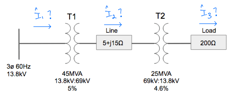
Per unit impedance in 3 phase systems.

Transformer impedance per phase. The transformer secondary is short circuited. However a rather simple test provides a practical method of measuring the equivalent impedance of a transformer without separating the impedance of the windings. The voltage at this point is called the impedance voltage.
When the impedance voltage is expressed as a per unit value on the transformer rated line to line voltage the impedance voltage is equivalent to the per unit impedance ie. Any per unit impedance will have the same value on both the primary and secondary of a transformer and is independent of voltage level. Voltage is increased on the primary until full load current flows in the.
A network of per unit impedances can then be solved using standard network analysis. One transformer will be working with a higher power factor and the other with a lower power factor than that of the combined output. This is because each winding is tested separately and normally quoted as a per unit or percent impedance voltage based on the transformers rated line to line voltage see ieee std c571290.
2 per phase pvc conduit 225 kva transformer. Where is the measured impedance voltage v is the rated transformer line to line voltage base voltage v. The impedance of a transformer is the total opposition offered to alternating current.
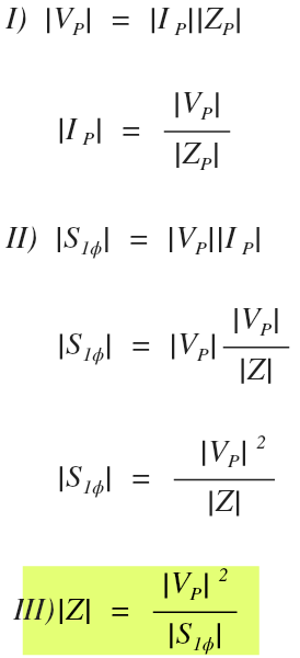
In a 3 phase system if z ohms line to neutral impedance in ohms per phase and va the 3 phase volt ampere base and v the base line to line voltage then. Transformer impedance z helps to determine what the short circuit current will be at the transformer secondary. This may be calculated for each winding.
Transformer impedance is determined as follows.

Short Circuit Calculations And Symmetrical Components Part 1

Ground Rules By John Cadick The Per Unit System Part 2

Power System Representation And Equations

Solved 3 2 Two Transformers A B Have The Following Spe

Three Identical 500 Kva 2300 230v Single Phase T

Base Impedance Do We Use Single Phase Or Three Phase

Transformers

Power System Analysis

Base Impedance Do We Use Single Phase Or Three Phase

Skm Power Tools Electrical Engineering Software Home Page

Per Unit System Ppt Download

Skm Power Tools Electrical Engineering Software Home Page
Comments
Post a Comment